Data Acquisition System:
A typical Data Acquisition System consists of individual sensors with the necessary signal conditioning, data conversion, data processing, multiplexing, data handling and associated transmission, storage and display systems.
In order to optimise the characteristics of the system in terms of performance, handling capacity and cost, the relevant sub systems can be combined together. Analog Data Acquisition System is generally acquired and converted into digital form for the purpose of processing, transmission, display and storage.
Processing may consist of a large variety of operations, ranging from simple comparison to complicated mathematical manipulations. It can be for such purposes as collecting information (averages, statistics), converting the data into a useful form (e.g., calculations of efficiency of motor speed, torque and power input developed), using data for controlling a process, performing repeated calculations to separate signals buried in the noise, generating information for display, and various other purposes.
Data may be transmitted over long distances (from one point to another) or short distances (from test centre to a nearby PC).
The data may be displayed on a digital panel or on a CRT. The same be stored temporarily (for immediate use) or permanently for ready reference later.
Data acquisition generally relates to the process of collecting the input data in digital form as rapidly, accurately, and economically as necessary. The basic instrumentation used may be a DPM with digital outputs, a shaft digitiser, or a sophisticated high speed resolution device.
To match the input requirements with the output of the sensor, some form of scaling and offsetting is necessary, and this is achieved by the use of amplifier/ attenuators.
For converting analog information from more than one source, either additional transducers or multiplexers are employed. To increase the speed with which information is accurately converted, sample-hold circuits are used. (In some cases, for analog signals with extra-wide range, logarithmic conversion is used.)
Data Acquisition System Block Diagram:
A schematic block diagram of a General Data Acquisition System (DAS) is shown in Fig. 17.1.
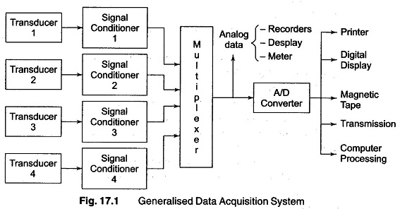
Transducers: They are converting physical quantities (such as temperature, pressure, etc.) into electrical quantities, or measuring electrical quantities directly. They collect data from the physical world.
The most commonly used transducers are:
- RTDs, thermocouples, and thermistors for temperature measurements.
- Photosensors for light measurements.
- Strain gages, piezoelectric transducers for force and pressure measurements.
- Microphone for sound measurements.
- Potentiometer, LVDT, optical encoder for position and displacement measurements.
Signal Conditioning Unit: The signal produced by the transducers may or may not be very suitable for our system to work properly. It may be very weak, very strong or may have some noise.
To convert this signal into the most suitable form, amplification, and filtration is done respectively by signal conditioning unit. So the signal conditioning unit converts electrical signals in the most suitable form.
Multiplexer: The multiplexer receives multiple analog inputs and provides a single output signal according to the requirements.
If a separate channel is used for each quantity, the cost of installation, maintenance, and periodic replacement becomes high. Therefore, a single channel is used which is shared by various quantities.
Analog to Digital (A/D) Converters: The data is converted into digital form by A/D converters.
After the conversion of data into digital form, it is displayed with the help of oscilloscopes, numerical displays, panel meters to monitor the complete system.
Also, the data can be either permanently or temporarily stored or recorded according to the requirement. The data is recorded on optical, ultraviolet, stylus or ink recorders for future use.
The characteristics of the data acquisition system, depend on both the properties of the analog data and on the processing carried out.
Based on the environment, a broad Classifications of data acquisition system into two categories.
- Those suitable for favourable environments (minimum RF interference and electromagnetic induction)
- Those intended for hostile environments
The former category may include, among other, laboratory instrument applications, test systems for collecting long term drift information on zeners, high calibration test instruments, and routine measurements in research, as mass spectrometers and lock-in amplifiers. In these, the systems are designed to perform tasks oriented more towards making sensitive measurements than to problems of protecting the integrity of analog data.
The Classifications of data acquisition system specifically includes measure, protecting the integrity of the analog data under hostile conditions. Such measurement conditions arise in aircraft control systems, turbovisous in electrical power systems, and in industrial process control systems.
Most of these hostile measurement conditions require devices capable of a wide range of temperature operations, excellent shielding, redundant paths for critical measurements and considerable processing of the digital data acquisition system.
On the other hand, laboratory measurements are performed over a narrow temperature range with much less electrical noise, employing high sensitivity and precision devices for higher accuracies and resolution.
The important Factors to Consider When Setting Up a Data Acquisition System are as follows.
- Accuracy and resolution
- Number of channels to be monitored
- Analog or digital signal
- Single channel or multichannel
- Sampling rate per channel
- Signal conditioning requirements of each channel
- Cost
The various general Configuration of Data Acquisition System are
- Single channel possibilities
- Direct conversion
- Pre-amplification and direct conversion
- Sample and hold, and conversion
- Pre-amplification, signal conditioning and any of the above
- Multi channel possibilities
- Multiplexing the outputs of single channel converters
- Multiplexing the output of sample-hold circuits
- Multiplexing the inputs of sample-hold circuits
- Multiplexing low level data
Objectives of Data Acquisition System:
- It must acquire the necessary data, at correct speed and at the correct
- Use of all data efficiently to inform the operator about the state of the
- It must monitor the complete plant operation to maintain on-line optimum and safe operations.
- It must provide an effective human communication system and be able to identify problem areas, thereby minimising unit availability and maximising unit through point at minimum cost.
- It must be able to collect, summarise and store data for diagnosis of operation and record purpose.
- It must be able to compute unit performance indices using on-line, real-time data.
- It must be flexible and capable of being expanded for future require
- It must be reliable, and not have a down time greater than 0.1%.
Comments
Post a Comment