Single Channel Vs Multi Channel DAS


Single Channel Data Acquisition System:

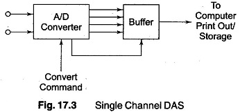
A Single Channel Data Acquisition System consists of a signal conditioner followed by an analog to digital (A/D) converter, performing repetitive conversions at a free running, internally determined rate. The outputs are in digital code words including over range indication, polarity information and a status output to indicate when the output digits are valid.

A Single Channel Data Acquisition System is shown in Fig. 17.3. The digital outputs are further fed to a storage or printout device, or to a digital computer device, or to a digital computer for analysis. The popular Digital panel Meter (DPM) is a well known example of this. However, there are two major drawbacks in using it as a DAS.

  1. It is slow and the BCD has to be changed into binary coding, if the output is to be processed by digital equipment.
  2. While it is free running, the data from the A/D converter is transferred to the interface register at a rate determined by the DPM itself, rather than commands beginning from the external interface.

Single Channel Data Acquisition System

Analog to Digital Converters (A/D):

Analog to digital converters used for DAS applications are usually designed to receive external commands to convert and hold. For dc and low frequency signals, a dual slope type converter is often used. The advantage is that it has a linear averaging capability and has a null response for frequencies harmonically related to the integrating period.

(Generally, the integrating time is selected equal to the period of the line frequency, since a major portion of the system interference occurs at this frequency and its harmonics.)

A/D converters based on dual slope techniques are useful for conversion of low frequency data, such as from thermocouples, especially in the presence of noise. The most popular type of converter for data system applications is the successive approximation type , since it is capable of high resolu­tion and high speed at moderate cost. (For a conversion time of 10 μS, the maximum dv/dt for full scale and 0.1% resolution is about 1 V/ms, which is a considerable improvement.)

Higher speeds are obtained by preceding the A/D converter by a sample hold (S/H). The sample hold is particularly required with successive approximation type A/D converters, since at higher rates of input change the latter generates substantial non-linearity errors because it cannot tolerate changes during the conversion process.

Direct digital conversion carried out near the signal source is very advanta­geous in cases where data needs to be transmitted through a noisy environ­ment. Even with a high level signal of 10 V, an 8 bit converter (1/256 resolution) can produce 1 bit ambiguity when affected by noise of the order of 40 mV.

Preamplification and Filtering:

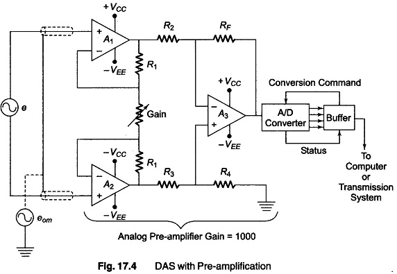
Many low resolution (8/10 bit) A/D converters are constructed with a single ended input and have a normalised analog input range of the order of 5-10 V, bipolar or unipolar. For signal levels which are low compared to input requirements, amplification may be used in order to bring up the level of the input to match converter input requirements, so that optimum use can be made in terms of accuracy and resolution. The amplifier used has a single ended input or a differential input, as shown in Fig. 17.4.

Single Channel Data Acquisition System

If the signal levels are below a tenth of an mV, or when resolution of 14 bits or 16 bits is needed, the use of differential amplifiers can become a necessity. . When differential output has to be handled from a bridge network, instru­mentation amplifiers are employed.

Single Channel DAS

The accuracy, linearity and gain stability specifications should be carefully considered, to ensure the system is not affected by any limitations.

If the input signals are to be physically isolated from the system, the conductive paths are broken by using a transformer coupled or an optocoupled isolation amplifier. These techniques are advantageous in handling signals from high voltage sources and transmission towers. In biomedical applications such isolation becomes essential.

Pre-amplifiers can be coupled with active filters before processing of data, in order to minimise the effect of noise carriers and interfering high frequency components. They effective compensate for transmission sensitivity loss at high frequency and hence enable measurements over an enhanced dynamic frequency range.

Special purpose filters, such as tracking filters, are used for preserving phase dependent data.

Multi-Channel DAS

Multichannel Analog Multiplexed System: 

The multichannel DAS system is shown in Figure. It has a single A/D converter preceded by a multiplexer.

As can be seen from the figure there are four inputs analog in nature. There can be number of inputs. Each signal is given to individual amplifiers. The output of the amplifiers is given to Signal condition circuits. From the output of the signal conditioning circuits the signals go to the multiplexer'. The multiplexer output is converted into digital signals by the A/D converters sequentially.
Multi Channel Data Acquisition System
 The multiplexer stores the data say of the first channel in the sample hold circuit. It then seeks the second channel. During this interval the data of the first channel will be converted into digital form. This permits utilization of time more efficiently.

When once the conversion is complete, the status line from the converter causes the sample/hold circuit to return to the sample mode. It then accepts the signal of the next channel. After acquisition of-data either immediately or on a command the sample hold circuit will be switched to the hold mode. Now conversion begins and the multiplexer selects the next channel.

This method is slow. Sample hold circuits or A/D converters are multiplexed for faster operation. However this method is less costly as majority of subsystems are shared. If the signal variations are very slow satisfactory accuracy can be obtained even without the sample hold circuit.

Multiplexing the Outputs of Sample/hold: 

This arrangement is called simultaneous sampled system multiplexer. The block diagram is shown in Figure. When large number of channels is to be monitored synchronously at moderate speeds this method is used.
Simultaneous Sampled System Multiplexer
The analog signals after signal conditioning are supplied to individual sample hold circuits. The sample hold circuits an updated synchronously by the timing circuit. The multiplexer receives the outputs of all the sample hold circuits. The multiplexer is connected to the A/D converter. This results in a sequential readout of the outputs.

Applications:

1. Wind tunnel measurements
2. Seismographic experiments
3. Radar
4. Fire control system

Multiplexing after A/D Conversion:

With the availability of A/D converters at considerably lower costs, it is feasible to use individual A/D converters for each analog channel. The available digital outputs of several A/D converters can be multiplexed.

The advantage here is that as the A/D conversion is on individual basis, the desired conversion rates can be used on individual channels.

Multichannel Das Using Digital Multiplexing
The parallel conversion scheme is shown in Figure. This type of scheme is advantageous in a data acquisition system that has several inputs distributed over vast plant area. The analog signals are converted into the required digital format at the source. Therefore transmission of data to the data centre can be made without line frequency and ground loop interferences. The data in the digital form will be used to perform logic operations and decisions. Depending on the relative speed at which data changes take place scanning rate can be increased or decreased.


It can be observed from the block diagram that one channel of the main digital multiplexed system has an input from a multiplexer. This arrangement is for input channels that have slowly varying data. Such slow varying data outputs from transducers can be pre-multiplexed in any of the available forms. This results in sequentially multiplexed sub-channel.

The sub-channel can be used as a channel feeding the main digital multiplexing system.

Multiplexing Low Level Data:

A single high quality data amplifier can be used for handling multichannel low level signal. Such an arrangement is shown in Figure.
Low Level Multiplexing
Each low level signal is provided with individual amplifier. Individual amplifier's output goes to sample hold circuit from which it is converted to the digital format. The input of the individual amplifiers can be either of the common mode type or differential type.

This type of multiplexing is useful when large numbers of channels with low level outputs are available. As high quality amplifiers are available with affordable cost providing individual amplifiers is possible. The following factors are to be considered to implement low level multiplexing satisfactorily.

1. Guarding is to be provided for each channel.
2. Proper switching of guard is necessary.
3. Signal to signal and common mode to differential cross-talk is to be avoided.
4. Capacitive balance is necessary.

Comments

Popular posts from this blog

Analog to Digital Converters: Successive Approximation A/D Converter

  Analog to Digital Converter & Its Working Almost every environmental measurable parameter is in analog form like temperature, sound, pressure, light, etc. Consider a temperature  monitoring system  wherein acquiring, analyzing, and processing temperature data from sensors is not possible with digital computers and processors. Therefore, this system needs an intermediate device to convert the analog temperature data into digital data in order to communicate with digital processors like microcontrollers and microprocessors. Analog to Digital Converter (ADC) is an electronic integrated circuit used to convert the analog signals such as voltages to digital or binary form consisting of 1s and 0s. Most of the ADCs take a voltage input as 0 to 10V, -5V to +5V, etc., and correspondingly produces digital output as some sort of a binary number. What is Analog to Digital Converter? A converter that is used to change the analog signal to digital is known as an analog to digital...

Digital Energy Meter

Digital Energy Meter What Is a Digital Energy Meter? An electric meter or energy meter is an essential device that goes with the consumption of commercially distributed energy. It enables systematic pricing of energy consumed by the individual consumers as it measures the amount of electrical energy consumed by a residence, business, or an electrically powered device [1]. They are typically calibrated in billing units, the most common one being the Kilowatts hour, which is equal to the amount of energy used by a load of one kilowatt over a period of one hour, or 3,600,000 joules. Some meters measured only the length of time for which charge flowed, with no measurement of the magnitude of voltage or current. These were only suited for constant-load applications. Neither type is likely to be used today. In addition to metering based on the amount of energy used, other types of metering are available. Meters which measured the amount of charge (coulombs) used, known as ampere-hour meters,...

Power Quality Analyzer

  Power Analyzer: Circuit Diagram & Its Working Power Analyzer  is the tool used to monitor the power quality. The rate of transfer of electricity in an electric circuit is known as Electric power. Electric power is measured in watts – joules per second in S.I units. There are various means to generate power. The  power  we utilize in our homes is usually produced by electric  generators  and supplied to homes, industries through the electric power grid. This task is done by the electric power industry. Unwanted variation in power quality could lead to breakdown or cause damage to sensitive equipment. Hence, it is crucial to monitor power quality frequently. What is Power Analyzer? A power analyzer, also known as a power quality analyzer, is the equipment used to monitor the power quality in devices. Power quality is usually understood as the compatibility between a power/electric source and load plugged in so that the load could function properly. When...