Compact Data Logger:
Compact Data Logger – A typical unit provides 60 channels of data in a 20 x 40 x 60 cm box weighing about 20 kg. Most manufacturers offer local or remote add-on scanners to expand to about 1000 channels. Scan rates are modest usually (1 — 20 channels per second) and though versatile signal conditioning is provided, the signal processing capability is limited to simple functions such as (mx + b) scaling, time averaging of single channels, group averaging of several channels, and alarm signaling when preset limits are exceeded. However, most units do allow interfacing to computers, where versatile processing is possible.
Compact Data Logger of this class utilise a built in microprocessor to control the interval of operations and carry out calculations through a single amplifier — A/D converter, which is automatically ranged or gain switched under program control to accommodate the signal level of each channel, as shown in Fig. 17.26.
This is not useful for applications in which fast changing signals must be observed, since a (typical) 5 channels per second scan rate takes 12 s to scan 60 channels before returning to any given channel. Also, the time skew of 12 s can cause a density error if the signals change too rapidly (for example, if gas density from a pressure on channel 1 and temperature on channel 60 is measured).
Often multiplexers (scanners) are available in both general purpose (two wire) and low level (two original wires plus shield) versions, since milli-volt level signals, such as from thermocouples, generally use a shielded, twisted pair of conductors. A three wire system scanner can reduce errors from about 10 to 1 μV. Electro-mechanical reed switches are used frequently in such scanners, since speed requirements are modest but low noise is important.
Since thermocouples are very common in Compact Data Logger applications, reference junction compensation and linearization options are always available. Reference-junction compensation can be offered economically and accurately for any mixture of thermocouple types by the use of an isothermal connection block. This thermocouple terminal block is designed to have an uniform (± 0.05°C) temperature (the reference junction) over its length. The block temperature is allowed to drift with ambient conditions, but is measured (often with a junction semiconductor sensor, since these work well near room temperature). This reference-junction temperature is sent to the microprocessor, where the temperature/voltage data for each thermocouple being employed is stored and the necessary correction is calculated. The microprocessor also stores the equations which curve-fit the thermocouple tables (over the desired range) for each thermocouple type, providing software linearization. For resistance thermometers the Compact Data Logger provide constant-current excitation and software linearizations.
The system amplifier and A/D converter are the crucial elements for overall system accuracy. Since Compact Data Logger inputs vary widely in voltage range, while the A/D input is typically fixed at +10 V, the microprocessor sets the amplifier gain at a proper value as each channel is sampled (some Compact Data Logger also provides automatic ranging). These range selections are entered from the front panel when the logger is programmed for the particular application. Programming of this and other functions is very simple, and do not require a knowledge of computer languages.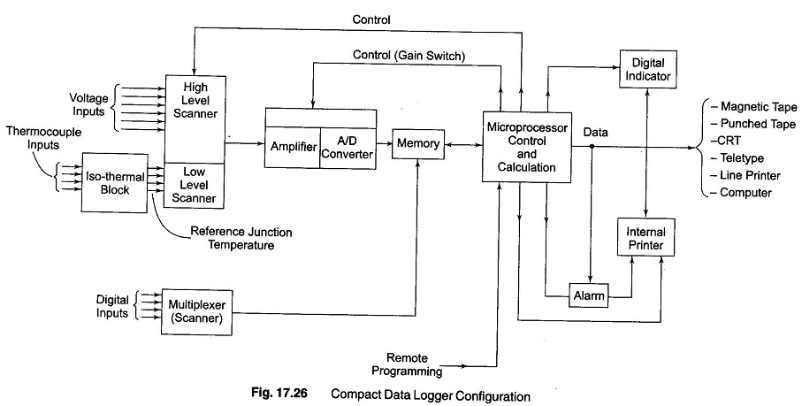
A typical set of ranges and resolutions would be ± 40 mV (1 μV resolution), ± 400 mV (10 μV resolution), ± 4 V (100 μV) and ± 40 V (1 mV) with a input impedance of 200 MΩ. (Except 10 MΩ on 40 V range). Zero drift is kept negligible by an automatic zero system.
A/D converters are often of the dual slope type or voltage to frequency type, since conversion speed is modest and these integrating converters give good noise rejection. Fast or slow scanning rates (say 15 versus 3 channels per second) may be selected, to allow a trade off between speed and accuracy, since as integration time is increased the integrating A/D noise rejection improves.
A readout obtained by means of a built in digital indicator and two colour printer (prints alarm in red), or channel number, date and time of day is a standard. When a built-in printer is used, the printer speed (2 to 4 channels per second) limits the overall speed, even though scanning without printing may be possible at 15 to 20 channels per second. The readout format is selected by front panel programming.
Some units provide a 5 years non-volatile program memory which preserves stored programs in case of power failure. Interface options for external magnetic tape, punched tape, CRT terminals, line printers and computers are usually obtainable.
Comments
Post a Comment