Power Analyzer: Circuit Diagram & Its Working
Power Analyzer is the tool used to monitor the power quality. The rate of transfer of electricity in an electric circuit is known as Electric power. Electric power is measured in watts – joules per second in S.I units. There are various means to generate power. The power we utilize in our homes is usually produced by electric generators and supplied to homes, industries through the electric power grid. This task is done by the electric power industry. Unwanted variation in power quality could lead to breakdown or cause damage to sensitive equipment. Hence, it is crucial to monitor power quality frequently.
What is Power Analyzer?
A power analyzer, also known as a power quality analyzer, is the equipment used to monitor the power quality in devices. Power quality is usually understood as the compatibility between a power/electric source and load plugged in so that the load could function properly. When power quality is low the load could get damaged or may malfunction. There are many causes of poor power quality.
Voltage, frequency of the signal, and waveform are the factors considered to measure power quality. When the power quantity has a steady supply voltage that stays in prescribed limits, and its A.C frequency is steady and close to the rated value with a smooth voltage curve, it is considered as good power quality.
The quality of power may vary due to discontinuity in service, variation in voltage magnitude, Transient currents, harmonics raising in A.C power. For power quality troubleshooting, the power analyzer helps in calibrating and eliminating issues such as dips in voltage, swells, harmonics, unbalance etc…seen in electric power.
Circuit Diagram
To understand the working of a power analyzer, let us look at its circuit.
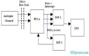
A typical power analyzer consists of two isolated channels for voltage and current input. The voltage input has an attenuator and the current input has a built-in current shunt. These inputs are sampled and this sampled data is analyzed by a high-speed Digital Signal Processing unit. It also contains an FPGA unit to interface all other units. A separate CPU is provided which takes the input from DSP for displaying results, storing them, and transmitting them over wireless channels.
Power Analyzer Connection
In the electric power industry, power is generated at the power generator. Then this power is transmitted on electric transmission lines, distributed over this network, and reaches the electricity meters present near the end-user. For effective monitoring of power in the network, Power analyzers are installed at three important positions – Main, Distribution switchboards, secondary switchboards.
Mains – This stage consists of devices with high performance and which requires accuracy for monitoring. Power analyzers used at this stage must have additional features.
Distribution Switchboards – Power analyzers at this stage are dedicated to registering electrical parameters and reporting alarm if any anomalies are found.
secondary Switchboards – These power analyzers are dedicated to monitor and log data of loads connected to the end of the transmission lines. These give full information on the status and power consumption of each load.
There are two methods for measuring electric parameters. Direct current measurement – for this type of measurement circuit should be open. Indirect current measurement – here current transformer clamp is connected to the wire to measure the current. Depending on the field of operation there are various types of power analyzers for distinct applications.
For maintenance and inspection tasks power analyzers with clamps are preferred. These do not require any extra connections. The three-phase power analyzer has three clamps to measure inputs simultaneously.
If the measuring current is within limits of the maximum rated input current of the power analyzer, the current-carrying cable can be directly connected to the power analyzer input. If the measuring current exceeds the rated input limits then an external current transformer is used to convert the current into a voltage or current signal so that the power analyzer could measure it directly.
Power Analyzer Working Principle
Power analyzers are used to measure power quality in Alternating Current circuits(AC) or Direct current systems(DC). For measuring power quality in AC circuits it uses distinct circuit considerations.
Modern power analyzers are portable and can transmit information using a wireless medium. Each channel of the analyzer consists of a switch to either an internal or external attenuator for voltage and stunt in case of current. This is followed by a high impedance buffer, a series of gain stages, and an A/D converter.
The Digital Signal Processor controls the gain and A/D conversions of the processed input. An autozero switch is provided at the front for DC accuracy.
This power analyzer can measure various parameters such as W, VA, VAr, power factor, phase, true r.m.s, fundamental harmonics, TIF, impedance, voltage surge, etc…The whole operation of the power analyzer can be controlled using a serial interface, LAN, or a GPIB interface.
The current shunt used here gives very wide bandwidth with a minimum phase shift. The voltage attenuator helps in achieving a wide bandwidth response which matches the current shunt response. Here, both the channels are calibrated digitally, removing the need for any physical adjustments.
Usually, measuring the electrical signal’s true RMS time period is considered as the crucial task of any measuring instrument. This measurement becomes a complicated task when applied to AC signals.
When it comes to AC signals to calculate the true RMS of an AC waveform, the average value has to be calculated across the AC frequency cycle. This is called the fundamental frequency of the circuit.
AC power analyzers display output as an analog waveform. An inbuilt oscilloscope is used here to display the output. In the case of DC power Analyzers, a display is used to display the digital digits.
Advanced Power Analyzer
Besides power measurements, an innovative power analyzer can provide information on various other factors. These advanced power analyzers are often used to measure mechanical energy values such as torque and speed. These are considered as critical factors in manufacturing applications.
This provides data for measuring the performance and efficiency of electromechanical systems. Some of the additional calculations performed by advanced power analyzers are:
- Efficiency Mapping.
- Fast Forward Transform.
- Harmonic analysis.
- Fundamental power.
- RMS values.
- Space vectors and DQ current, and
- Polar diagrams and symmetrical components.
Power Analyzer Measurements
Depending on the manufacturer and model, a power analyzer can make various measurements. But some of the typical measurements that every power analyzer must calculate are Voltage, Current, Power, Peak parameters of voltage, Mean Parameters, RMS values, Harmonics, phase, etc.. Modern power analyzers often have capabilities to store data and data logging. This data is usually stored onboard and can be downloaded at a later time or displayed on the screen.
Power analyzers also come with the capacity to communicate data or share it via ethernet or USB with other computers for further analysis.
Applications
With the increase in usage of electronic items and increased sensitivity in electrically operated loads, power quality measurement has become an important task. Some of the other applications for power analyzer are as follows:
- To identify the electrical issues.
- Record the total cost of electrical energy consumed.
- To obtain information about various electrical variables in real-time to achieve maximum energy efficiency.
- To control and reduce the unnecessary usage of power.
- Accurate power measurements for Variable speed motor drive analysis.
- Measure the efficiency and power quality of LED drivers.
- Standby power analysis using the software.
The utilities, substations, electric power industry contains various transformers, generators, and electrical distribution networks. To maintain the ideal functioning of such systems regular monitoring and troubleshooting equipment such are power analyzers are necessary. Simply connect the tool, view the status either numerically or graphically, log the data, and share with other systems for further analysis.
Power Quality Analyzer Explained
A power quality anayzer is used to measure electric power signals to determine the load's ability to function properly with that electric power. Without the correct electric power, electrical equipment may fail prematurely or malfunction. There are many different different factors that contribute to poor quality power.
Power quality analyzers, such as any Fluke Series meter, track several electrical parameters, which include AC voltage, AC current power, and frequency. Electrical data parameters include demand and peak demand. Electrical demand is the actual amount of power that the monitored system uses. Peak electrical demand is the maximum amount of electric power that can be used. Typically, power parameters are measured in watts (W), volt amperes (VA), and volt ampere reactives (VAR). Watts are units of electrical power that indicate the rate of energy produced or consumed by an electrical device. Volt amperes equal the current flowing in a circuit multiplied by the voltage of that circuit. Volt ampere reactives identify the reactive component of volt amperes.
Fluke power quality analyzers and power meters detect mystery disturbances: those upsets to a process or sensitive equipment operation that don't seem to correspond to any identifiable source of power disturbance. Such things as ground loops, high speed transients, lightning, and common mode electrical noise come to mind. Many of these events are here and gone in such a short time frame that they are not easily identified, except with a power disturbance analyzer using highspeed wave shape or event capture.
A Fluke power quality meter can also detect repetitive, cyclical disturbances both within and outside of a facility. These problems will be repetitive and cyclical in nature, definitely power-related, and line-to-line. Examples include voltage sags and surges, momentary interruptions by circuit breaker operations, and power interruptions.
A power quality analyzer can also measure harmonic distortion, a disturbance related to the integer multiples of the fundamental power frequency (60 Hz). WIt is widely recognized that this area is a subset of the power related area, since harmonic currents and voltages are recurring. However, there may need to be special tactics in searching out these problems and identifying our solution alternatives.


Comments
Post a Comment