Maxwell’s inductance bridge

 Maxwell's Bridge

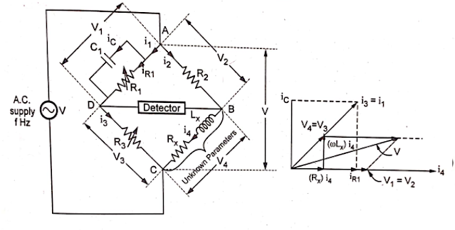
Maxwell's bridge can be used to measure inductance by comparison either with variable standard self-inductance or with a standard variable capacitance. These measurements can be done by using Maxwell's Bridge in two different forms.

Maxwell's Inductance Bridge

Using this bridge, We can measure inductance by comparing it with a Standard variable self-inductance arranged in a bridge circuit as shown in Fig.  (a).
Consider Maxwell's inductance bridge as shown in Fig  (a). Two branches consist of non-inductive resistances R1 and R2. One of the arms consists of Variable inductance with series resistance r. The remaining arm consists of unknown inductance Lx.


Maxwell's Inductance Capacitance Bridge

Using this bridge, we can measure inductance by comparing it with a variable standard capacitor. The bridge circuit diagram is shown in Fig.

One of the ratio arms consists of resistance and capacitance in parallel. Hence it is simple to write the bridge equations in the admittance form.
The advantages of using standard known capacitors for measurement are :
1) The capacitors are less expensive than stable and accurate standard inductors
2) The capacitors are almost lossless.
3) External fields have less effect on a capacitor. The standard inductor requires shielding in order to eliminate the effect of stray magnetic fields.
4) The standard inductor will not present its rated value of inductance flow through it is precisely adjusted.
5) The capacitors are smaller in size.
This bridge is also called the Maxwell Wien bridge.

Advantages of Maxwell Bridge:
1) The balance equation is independent of losses associated with inductances.
2) The balance equation is independent of the frequency of measurement.
3) The scale of the resistance can be calibrated to read the inductance directly.
4) The scale of R1 can be calibrated to read the Q value directly.
5) When the bridge is balanced, the only component in series with the coil under test is resistance R2. If R2 is selected such that it can carry high current, then heavy current-carrying capacity coils can be tested using this bridge.

Limitations of Maxwell Bridge

1) It cannot be used for the measurement of high Q values. Its use is limited to the measurement of low Q values from 1 to 10.
2) There is an interaction between the resistance and reactance balances. Getting the balance adjustment is a little difficult.
3) It is unsuited for the coils with low Q values, less than one, because of the balance convergence problem.
4) The bridge balance equations are independent of frequency. But practically, the properties of the coil under test vary with frequency which can cause errors.

Commercial Maxwell bridge measures the inductance from 1 - 1000 H, wi ± 2 % error.


Comments

Popular posts from this blog

Analog to Digital Converters: Successive Approximation A/D Converter

  Analog to Digital Converter & Its Working Almost every environmental measurable parameter is in analog form like temperature, sound, pressure, light, etc. Consider a temperature  monitoring system  wherein acquiring, analyzing, and processing temperature data from sensors is not possible with digital computers and processors. Therefore, this system needs an intermediate device to convert the analog temperature data into digital data in order to communicate with digital processors like microcontrollers and microprocessors. Analog to Digital Converter (ADC) is an electronic integrated circuit used to convert the analog signals such as voltages to digital or binary form consisting of 1s and 0s. Most of the ADCs take a voltage input as 0 to 10V, -5V to +5V, etc., and correspondingly produces digital output as some sort of a binary number. What is Analog to Digital Converter? A converter that is used to change the analog signal to digital is known as an analog to digital converter or

Digital Energy Meter

Digital Energy Meter What Is a Digital Energy Meter? An electric meter or energy meter is an essential device that goes with the consumption of commercially distributed energy. It enables systematic pricing of energy consumed by the individual consumers as it measures the amount of electrical energy consumed by a residence, business, or an electrically powered device [1]. They are typically calibrated in billing units, the most common one being the Kilowatts hour, which is equal to the amount of energy used by a load of one kilowatt over a period of one hour, or 3,600,000 joules. Some meters measured only the length of time for which charge flowed, with no measurement of the magnitude of voltage or current. These were only suited for constant-load applications. Neither type is likely to be used today. In addition to metering based on the amount of energy used, other types of metering are available. Meters which measured the amount of charge (coulombs) used, known as ampere-hour meters,

Power Quality Analyzer

  Power Analyzer: Circuit Diagram & Its Working Power Analyzer  is the tool used to monitor the power quality. The rate of transfer of electricity in an electric circuit is known as Electric power. Electric power is measured in watts – joules per second in S.I units. There are various means to generate power. The  power  we utilize in our homes is usually produced by electric  generators  and supplied to homes, industries through the electric power grid. This task is done by the electric power industry. Unwanted variation in power quality could lead to breakdown or cause damage to sensitive equipment. Hence, it is crucial to monitor power quality frequently. What is Power Analyzer? A power analyzer, also known as a power quality analyzer, is the equipment used to monitor the power quality in devices. Power quality is usually understood as the compatibility between a power/electric source and load plugged in so that the load could function properly. When power quality is low the loa