If the electrical components are arranged in the form of a bridge or ring structure, then that electrical circuit is called a bridge. In general, a bridge forms a loop with a set of four arms or branches. Each branch may contain one or two electrical components.
Types of Bridges
- DC Bridge
- AC Bridge
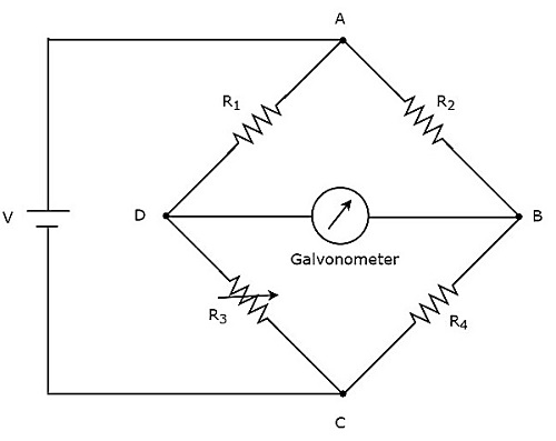
The above DC bridge has four arms and each arm consists of a resistor. Among which, two resistors have fixed resistance values, one resistor is a variable resistor and the other one has an unknown resistance value.
The above DC bridge circuit can be excited with a DC voltage source by placing it in one diagonal. The galvanometer is recognised in other diagonals of the DC bridge. It shows some deflection as long as the bridge is unbalanced.
Vary the resistance value of the variable resistor until the galvanometer shows null (zero) deflection. Now, the above DC bridge is said to be a balanced one. So, we can find the value of unknown resistance by using nodal equations.
The two types of d.c. bridges are,
1. Wheatstone bridge 2. Kelvin bridge
AC Bridges
If the bridge circuit can be operated with only AC voltage signal, then it is said to be AC bridge circuit or simply AC bridge. AC bridges measure the value of unknown inductance, capacitance and frequency.The circuit diagram of the AC bridge looks as shown in the below figure.
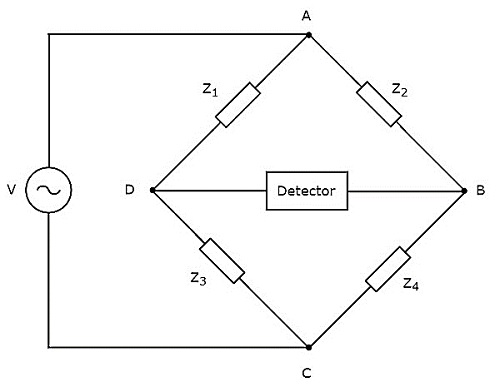
The circuit diagram of the AC bridge is similar to that of the DC bridge. The above AC bridge has four arms and each arm consists of some impedance. That means each arm will be having either single or a combination of passive elements such as a resistor, inductor and capacitor.
Among the four impedances, two impedances have fixed values, one impedance is variable and the other one is an unknown impedance.
The above AC bridge circuit can be excited with an AC voltage source by placing it in one diagonal. A detector is placed in another diagonal of AC bridge. It shows some deflection as long as the bridge is unbalanced.
The above AC bridge circuit can be excited with an AC voltage source by placing it in one diagonal. A detector is placed in other diagonal of AC bridge. It shows some deflection as long as the bridge is unbalanced.
Vary the impedance value of variable impedance until the detector shows null (zero) deflection. Now, the above AC bridge is said to be a balanced one. So, we can find the value of unknown impedance by using balanced condition.
The various types of a.c. bridges are,
3. Maxwell's bridge
5. Anderson bridge
2. Inductance comparison bridge
4. Hay's bridge
6. Schering bridge
7. Wien bridge
Wheatstone’s Bridge
The bridge consists of four resistive arms together with a source of e.m.f. and a null
detector. The galvanometer is used as a null detector. The Wheatstone bridge is used to measure the resistances in the range 1 ohm to a few megaohms.

The arms consisting of the resistances R1 and R2 are called ratio arms. The arm consisting of the standard known resistance R3 is called the standard arm. The resistance R4 is the unknown resistance to be measured. The battery is connected between A and C while the galvanometer is connected between B and D.
Balance Condition
The bridge is balanced, the galvanometer carries zero current and it does not show any deflection. Thus bridge works on the principle of null deflection or null indication.
To have zero current through a galvanometer points B and D must be at the same potential. Thus potential across arm AB must be the same as the potential across arm AD.

This is the required balance Equation for Wheatstone Bridge.
1.It depends on the ratio of RI and R2 hence these arms are called ratio arm.
2. As it works on a null indication, the results are not dependent on the calibration and
characteristics of a galvanometer.

- The Wheatstone bridge is basically a d.c. bridge an use in the range 1 ohm to low megaohm.
- It is used to measure the d.c. resistance of various types of wires for the purpose of quality control of wire.
- It is used to measure the resistance of motor winding, relay coils etc.
- It is used by the telephone companies to locate the cable faults. The faults may be of the type line to line short or line-to-ground short.
- The results are not dependent on the calibration and characteristics of galvanometer as it works on null deflection.
- The source e.m.f. and inaccuracies due to the source fluctuations do not affect the balance of the bridge. Hence the corresponding errors are completely avoided.
- Due to null deflection method used, the accuracy and sensitivity is higher than direct deflection meters.
- The effect of lead resistance and contact resistance is very much significant while measuring low resistances.
- The bridge cannot be used for high resistance measurement i.e. measurement in a high megaohm range. This is because while such measurement the resistance presented by the bridge becomes so large that the galvanometer becomes insensitive to show any imbalance.
- Similarly, heating effect due to the large current also plays a major role. Excessive currents may generate heat which may cause a permanent change in the resistance.
- The resistance used must be very precise having tolerance upto 1% or 0.1 % hence cost is high.
Comments
Post a Comment