Digital Voltmeter (DVM)
Definition: Digital Voltmeter is a voltage-sensitive device. It measures AC or DC voltage and displays the value directly in numeric form instead of pointer deflection. DVM is an acronym for Digital Voltmeter. DVM was first invented in 1954 by Andrew Kay.
There exist many factors that affect the measurement accuracy of a digital voltmeter(DVM). These are basically temperature, input impedance, variation in power supply voltage etc.
As we know that an analogue instrument provides results by pointer deflection on a continuous scale. On contrary, a digital instrument provides results as discrete numerals. Thus providing accuracy and versatility together.
The input range of DVM may vary from ±1 V to 1000 V. Precision DVM offers input resistance of 1 GΩ or high for a voltage range of less than 20 V.
Block diagram of Digital Voltmeter
The figure below shows the block diagram of a typical digital voltmeter.
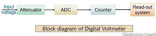
As we can see, the block diagram consists of attenuator with an analogue to digital converter after it. This ADC unit basically distinguishes between various types of Digital Voltmeters which we will discuss later.
A counter section is also employed in the circuitry that is usually a decade counter. The read-out system is used to display the digital voltage of the input signal.
Working of Digital Voltmeter
Let us now have a look at the detailed diagram of a Digital Voltmeter. The figure below will help you to understand the working of a DVM.
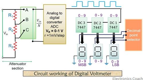
The attenuator section consists of a series of resistance that attenuates the input signal. The voltage at point A will be exactly the same as the input voltage Vin.
By the voltage division rule it is clear that the voltage at B will be less than the voltage at A. Similarly, the voltage at C will definitely be less than the voltage at both the points A and B. So, in this way an attenuator section works.
Now, the thing that comes to our mind is what is the need for this attenuator at the beginning of the circuit?
So, the reason for this is, an attenuator placed here minimizes the excess voltage that can damage the other components of the device. It is basically a predefined resistive network that performs attenuation for circuit protection.
Here, the attenuation is termed as decade attenuation as it is a digital voltmeter and we require decimal count. That means if attenuation occurs it will be in powers of 10.
So, at the input of ADC, we will have Vin/N as the input voltage.
: N = 1, 10, 100, 1000
The ADC employed in the circuit converts analogue signal into digital one in order to provide the digital output. A digital signal is the one having 2 levels i.e., 0 and 1.
So, the input at ADC Vin/N gets converted into digital signal. This will provide us a sequence of digital pulses. One pulse for 1 mV as at the ADC we have taken resolution as 1 mV/step.
These digital pulses are then fed to the counter unit. Here, we have used a decade counter. A decade counter counts in decimal inspite binary.
The counter unit on a whole consist of 3-decade counters that are cascaded together. These decade counters have the ability to count from 0-9 i.e., 10 counts. Hence the three will count up to 1000.
DC 7447 converts the BCD value into 7 segment display. That means now the input value will be displayed here in digital format. The decimal point selector at the end of the circuit will select the position of decimal according to the magnitude of the voltage.
Types of Digital Voltmeter
The classification of DVM is based on different ADC conversion methods-
- Ramp type DVM
In a ramp-type DVM, the operation basically depends on the measurement of time. The time that a ramp voltage takes to change from the level of the input voltage to that of 0 voltage or vice versa. An electronic time interval counter is used to measure the time interval and the count is displayed in digits as voltmeter output.
Let us have look at the block diagram and operating principle of a ramp-type DVM.
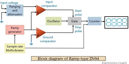
Here, as we can see in the figure below a negative going ramp voltage is shown. This ramp voltage is compared with the unknown voltage. An input comparator employed in the circuit generates a pulse when ramp voltage becomes equal to the voltage under measurement.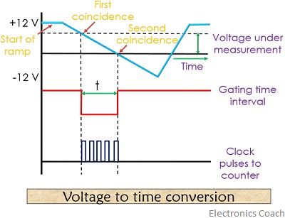
Now, the ramp voltage falls to reach 0 value. The ground comparator employed in the circuit generates stop pulse. This stop pulse closes the gate.
The gate opening time duration is proportional to the value of input voltage. The sample rate Multivibrator employed here is used to find the rate by which the measurement cycle begins.
2. Dual slope integrating type DVM
The figure below shows the block diagram of dual slope integrating type DVM.
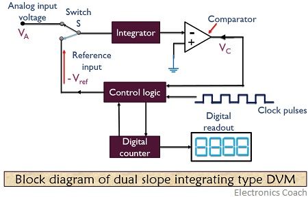
For a fixed time interval, the analogue input is applied to the integrator via switch S. The level of the input voltage is raised in the comparator to some desired positive value as we can see in the figure below.
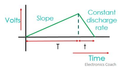 At the end of a fixed time interval, the rate of increase in voltage will be proportional to the input voltage.
At this time the count is set at 0 and the switch gets shifted to reference voltage. Now, the output of the integrator will start decreasing and drop until it reaches below the comparator reference voltage. At this time control logic will receive a signal in order to stop the count.
The count shown by the counter that is proportional to input voltage will be the measured value and hence displayed at the Digital read-out.
3. Integrating type DVM
In this category of Digital Voltmeter, the true value of input voltage is measured over a fixed measuring time.
Here, an integration technique is employed that uses voltage-to-frequency conversion. This voltage-to-frequency converter act as a feedback control system. This basically governs the pulse generation rate is proportional to the magnitude of applied input voltage.
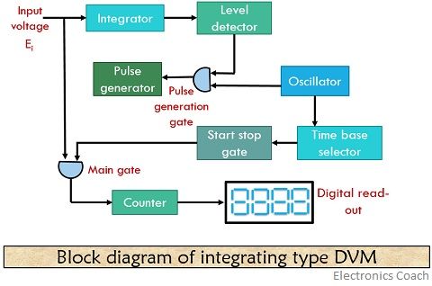
In voltage to frequency conversion technique, a train of pulses is generated. The frequency of these pulses depends on the voltage being measured.
Then these pulses are counted that appears in a definite time interval. After all, the frequency of pulses is a function of input voltage, the number of pulses is an indication of the input voltage.
4. Successive Approximation DVM
In this category of DVM, the ADC employed makes use of successive approximation converter. Thus it is named as so. These are capable of 1000 readings per second.
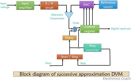
In the beginning, a start pulse is applied at the start/stop Multivibrator. Due to this, MSB of the control register is set to high and all other bits to low. So, for an 8-bit control register, the reading would be 10000000.
Thus causing the output of DAC to be half of the reference voltage.
Now, the comparator compares the output of the converter from the input voltage and produces an output that will cause the control register to retain 1 in its MSB.
The ring converter employed in the circuit advances one count next thus shifting a 1 in the second. This will cause the MSB of the control register and its reading to be 11000000.
Thus DAC increases its reference by one increment and another comparison of input voltage with that of reference takes place. In this way through successive approximation the measurement cycle proceeds. On reaching the last count, the measurement cycle stops.
The output in digital format at the control register shows the final approximation of input voltage.
Advantages of Digital Voltmeter
- DVM provides numerical readouts that eliminate observational errors. Thus providing better readability.
- DVM offers better accuracy and versatility as compared to analogue voltmeters.
- DVM has a greater speed of taking voltage readings as compared to analogue instruments.
- The output of DVM can be fed to memory devices for further computations.
- The decreased size of DVM increases the portability if the instrument.
DVM offers an accuracy of 0.5% + 1 digit and the operating temperature range is -5 ⁰C to 55 ⁰C.
Comments
Post a Comment